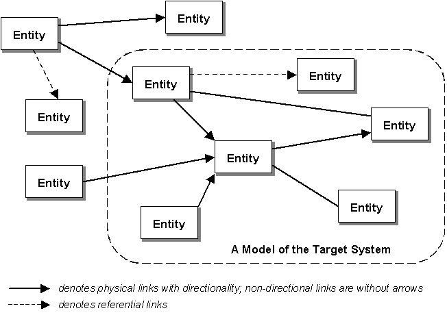
A model is a representation of a real world system under investigation. The tools used by the investigator to build the model affect how one abstracts the elements from the target system. With the SansGUI Object System, users abstract real world systems into entities and their relations. Each entity contains a set of properties and some operations that act upon these properties. The relations are represented by either physical or referential links. The physical links can be directional or non-directional, depending on the nature of the relation. We use non-directional links to represent bidirectional relations. The referential links are symbolic pointers contained in entities that need to access information in other entities. The meanings of these entities and their relations are given by simulation developers with domain specific definitions. Because of its generality, the SansGUI Object System can be used by simulators from different application fields, resulting in a learn-it-once-and-for-all, unified graphical user interface.

In an electronic model, the base entities can be resistors, capacitors, diodes, etc. and the links can be wires. In a hydraulic system, there are fluid sources, valves, turbines, etc. and the links can be pipes or orifices. For mechanical systems, the entities can be the mechanical components while the links are connections that carry force, heat, pressure, and so on, from one component to the other. There can also be servers, routers, gateways, and client nodes in communications networks. We can also apply this modeling scheme to many other fields, such as physical systems, control systems, artificial neural networks, and others. The entities and their relations depend upon abstraction and modeling in the particular domain.
As the number of entities in a model grows, it becomes harder to enter the associated values into all the entities and keep track of them. To simplify the task, SansGUI uses objects as containers to store common properties of multiple entities. An object, in a narrower sense in SansGUI, represents common features or properties of a group of entities in the model.
Because there are physical entities and informational entities, there are component objects and reference objects, respectively, in the SansGUI Object System. SansGUI treats component and reference objects in a slightly different manner.
A component object represent a group of physical entities. Different component entities can be derived from the same object so that each entity inherits the common values from the object. To eliminate the need to create an object for each entity that varies by only a few properties, SansGUI allows derived entities to have overriding values. When an overriding value is present in a derived entity, the overriding value will be used; otherwise, the value stored in the object will be used during initialization. To allow value overriding is optional; it is defined by the simulation developer. The component object and its derived entity imply an IS-A relation.
A reference object contains information referred to by other entities or objects. A reference object cannot be used to derive new entities in the SansGUI Object System. It can, however, be referred to by many other entities. The entities may contain one or more symbolic references in their properties to point to reference objects. Entities and their reference objects can be used to implement HAS-A relationship.
More details on Components and References can be found in the next section.
An Object Library contains the schema definitions of all classes related to a simulator and some objects created by the simulation developer. Although the organization of an Object Library is a development feature, simulation users can store commonly used objects in a customized Object Library and use it for later Project Model creation and for easy access. SansGUI supports:
Importing objects from an Object Library during Project Model creation time,
Using compatible objects selected into a global Object Toolbox in a Project Model, and
Dragging and dropping of compatible objects across Object Library and Project Model boundaries.
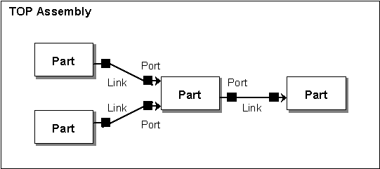
Physical entities that are derived from component objects and placed into the modeling space are parts. As explained previously, a part can have overriding values that make it slightly different from other parts derived from the same object. Two Parts can be physically connected by a link, so that the state of a part can affect that of the other. The link essentially carries information from one part to the other and is defined by the simulation developer. Just like parts, links are also derived from link objects and common link properties can be stored in link objects for reuse.
A link connects two parts via a port in each part. The ports are automatically created with rules set by the simulation developer. They are identified by a port number.
Uniqueness: The identification number may or may not be unique (whether or not a port can be reused), depending on the nature of the port set by the simulation developer.
Orientation: A port may be limited to a certain sides (top, bottom, left, or right) of the part it belongs to.
Direction: A port may be specified as input only, output only, or both.
Odd-Even Rule: An input port may be limited to use an odd number and an output port may be limited to use an even number.
Special Port 0: Port number 0 may be used for special purpose, defined by the simulation developer.
Auto Increment: The default port number will be generated with an increment of 1 when a link is created to connect to the part.
Ports may also have properties, such as opening diameters of a T-junction in a pipeline system. In SansGUI Object System 1.0, these port properties are defined in the component objects and cannot be overridden at the part level.
Parts connected with links in the modeling space form an assembly. There is always a TOP assembly in a Project Model. The following figure summarizes all the terms used SansGUI in an assembly level.

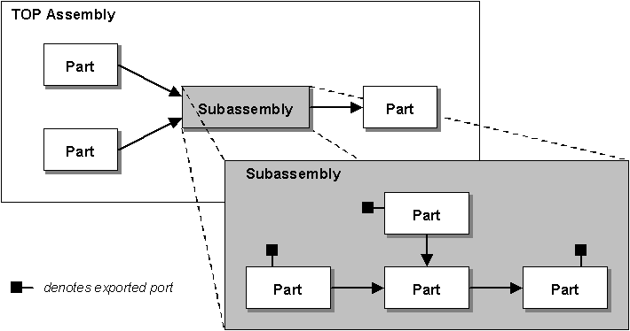
The SansGUI Object System supports assemblies in a tree structure in the modeling space. The advantages of using subassemblies in a multi-level assembly structure are:
Complex parts and links can be confined in a subassembly for clarity.
Groups of parts in subassemblies are easier to manage than those all lumped into a single TOP level.
Subassembly replication is useful when similar groups of parts and links exist in the model.
Hierarchical levels of subassemblies closely match the organization of the target system.

The SansGUI Object System uses a generic assembly object for creating parts that contain subassemblies. Initially, the generic assembly parts cannot be linked with other parts at the same level because there is no port definitions. However, certain ports in the parts at the subassembly level can be exported so that they can be used to link to other parts in this upper level. The ports can be further exported to yet another upper level for connections at that level or beyond. Exported ports may be assigned with a port number different from the port number of the part at the subassembly. The reason for this reassignment is for clarity at the upper assembly level.
Interestingly, the parts, links, ports and assemblies described above are all optional in the SansGUI Object System. There may be models without any part at all because the simulator requires only some referential data. There may also be models with only a single part, with only a single level assembly, or with levels of subassemblies. In all cases, an empty TOP assembly is generated by SansGUI during Project Model creation time.
Read the Advanced SansGUI Object System in the Developer's Guide and the SansGUI Reference Manual for more formal details.
SansGUI Modeling and Simulation Environment Version 1.2
Copyright © 2000-2003 ProtoDesign, Inc. All rights reserved.