To calculate
we create a computation flow graph as following:
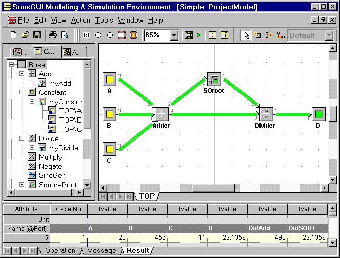
We implement the right-hand-side variables, A, B, and C as constants so that the values will not be wiped off when the user clicks on the Reset Data button in the Run toolbar. They are created from the myConstant object, derived from class Constant. Part D in the left-hand-side of the equation is a variable. It is derived from the myVariable object of Class Variable. The Adder, SQroot and Divider are operators that act on the input values carried by the input links and produce resulting values which are passed on to the output links. The calculation flow is controlled by a Vertical Scanline flag in the Default simulation control object under the SimControl.Cycle.Calc class. It means that the order of calculations is guided by vertical scan lines going from left to right and, for each scan line, from top down. Each time a part is encountered, its evaluation routine is executed. Thus, the Adder with inputs A, B, C will be performed first, and the sum will be deposited to the two output links for the evaluation of SQroot and Divider in sequence. Finally, the quotient from the division operation will be stored in D. The evaluation order of parts can be by: name (lexical order), Z-order (from back to front), vertical scanline (moving from left to right, top down in each line), horizontal scanline (moving from top to bottom, left to right in each line), or at random. In this case, it is set to vertical scanline. The user can change it to suit his or her needs.
Ports in the components are explicitly defined to identify input or output connections. In general, Port 1 indicates an input port and Port 2 indicates an output port. For the division operation, we need to distinguish the dividend from the divisor(s). We define a unique Port 0 for the single dividend and non-unique Port 1 for divisors because there can be more than one divisor. All the components can have multiple output ports but some may have only one unique input port, such as the Variable and the SQroot parts.
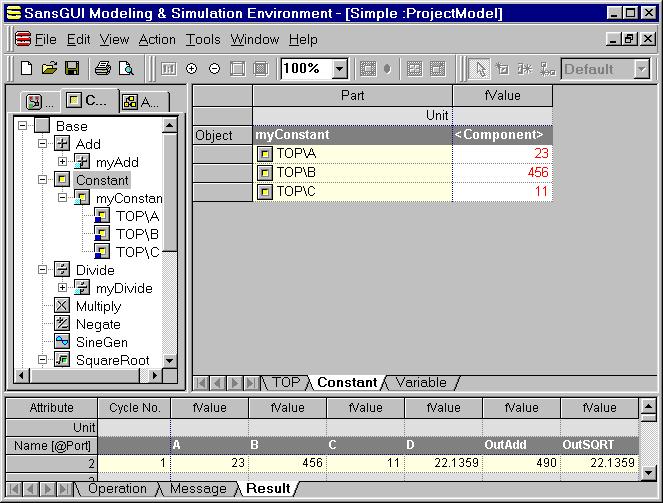
The simulation is executed in a single cycle with the values logged in the Result View in the Bottom Pane. As a test, we simply entered the values of 23, 456, and 11 as part override values in A, B, and C, respectively. The TOP\ prefix means that these parts are located in the TOP assembly. You can click on the Constant class in the Tree View to reveal all the variables in a Grid View in the Right Pane and enter the new input values directly. The numbers are shown in red, meaning that those are part override values.
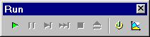
To test other sets of values, enter them into the fValue column of A, B, and C parts and then click on the Run In-Process button (the right pointed triangle on the toolbar) to see the value changes in the Result View in the Bottom Pane.
If SansGUI displays an error about the simulator DLL not found or you would like to run the DLL from your modified calculator project, you need to change the Simulator Program Path field in the simulation control object. To do so, simply:
Click on the first Object tab in the Left Pane to show the simulation control object in the Tree View.
Find the Default object under SimControl.Cycle.Calc class path. Double click on its name or icon.
An Object Properties dialog is shown as following:
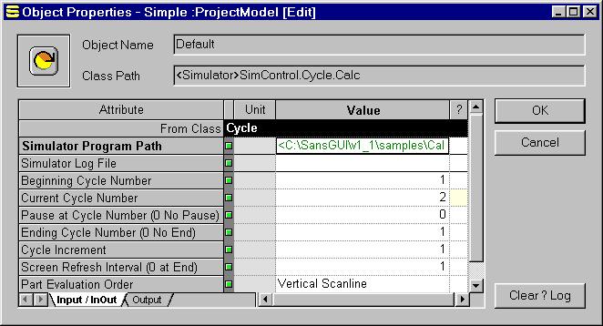
Right click on the Value cell of the Simulator Program Path field. A context menu will appear. Select Input Assistant.
Inside Input Assistant, click on the <File/Dir>... button.
Use the File selection dialog to locate the Calc_1_1.DLL (C/C++) or Calc_1_1F.DLL (Fortran) executable file under one of the following directories:
![]() Samples\Calc\Calc_1_1\Release:
for the release build of the calculator engine in C/C++.
Samples\Calc\Calc_1_1\Release:
for the release build of the calculator engine in C/C++.
![]() Samples\Calc\Calc_1_1\Trace:
for the debug build of the calculator engine in C/C++.
Samples\Calc\Calc_1_1\Trace:
for the debug build of the calculator engine in C/C++.
![]() Samples\Calc\Calc_1_1F\Release:
for the release build of the calculator engine in Fortran.
Samples\Calc\Calc_1_1F\Release:
for the release build of the calculator engine in Fortran.
![]() Samples\Calc\Calc_1_1F\Debug:
for the debug build of the calculator engine in Fortran.
Samples\Calc\Calc_1_1F\Debug:
for the debug build of the calculator engine in Fortran.
Click on the Open button to set the DLL file and then click on the OK buttons to close all the dialogs.
Alternatively, you can copy any one of the DLL file (release build preferred) to the sim simulator installation subdirectory and wipe off the Simulator Program Path value to use the copied file in the default location. When using the Fortran implementation, you need to remove the F suffix in the DLL name and call it Calc_1_0.DLL under the sim directory.
Visual Calculator for SansGUI Version 1.1
Copyright © 2001-2003 ProtoDesign, Inc. All rights reserved.